WHAT IS A MODE CONDITIONING PATCH CABLE?
Optical Mode Conditioners provide a convenient and reliable method of connecting multimode fiber plants with 1000Base- LX based transmission equipment compliant with IEEE 802.3 standards. Mode conditioners provide a method of offsetting a single-mode fiber core with a corresponding multimode fiber. This calibrated offset reduces a phenomena called differential mode dispersion, or DMD, which can cause the transmitting laser pulse to spread out and merge into neighboring pulses creating bit errors in the transmission signal.Mode conditioners are built in the form of a simple duplex patch cable, so they can easily be installed in a system without the need for additional components or hardware. Their length can range from one meter and up to support virtually any network topography.
The need for this patch cord is due to the single-mode launch nature of the -LX (1300nm) transceiver modules used for Gigabit Ethernet. These modules have to operate for both single-mode and multimode fibers. Launching a single-mode laser into the center of a multimode fiber can cause multiple signals to be generated that confuse the receiver at the other end of the fiber. These multiple signals, caused by Differential Mode Delay (DMD) effects, severely limit the cable distance lengths for operating Gigabit Ethernet. A mode conditioning patch cord eliminates these multiple signals by allowing the single-mode launch to be offset away from the center of a multimode fiber. This offset point creates a launch that is similar to typical multimode LED launches.
Things to know when using mode conditioning cables to patch an existing multimode cable plant to your Gigabit LX equipment.
- Usually used in pairs, mode conditioning cables usually require a MC cable at each end to connect the equipment to the cable plant. The only reason to order an odd number of mode conditioning cables is to have a spare on hand.
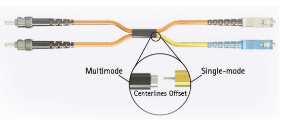
- If your Gigabit LX switch is equipped with SC or LC connectors, please be sure to connect the yellow leg (single-mode) of the cable to the transmit side, and the orange leg (multimode) to the receive side of the equipment. It is imperative that this configuration be maintained on both ends. The swap of transmit and receive can only be done at the cable plant side. See diagram below.
This white paper is for informational purposes only and is subject to change without notice. C2G makes no guarantees, either expressed or implied, concerning the accuracy, completeness or reliability of the information found in this document.