THE INFORMATION TRANSMISSION SEQUENCE AND TYPES OF FIBER
As shown below, information (voice, data or video) is encoded into electrical signals. At the light source these electrical signals are converted into light signals. It is important to note that fiber has the capability to carry either analog or digital signals. Many people believe that fiber can transmit only digital signals due to the on/off binary characteristic of the light source. The intensity of the light and the frequency at which the intensity changes can be used for AM and FM analog transmission. Once the signals are converted to light, they travel down the fiber until they reach a detector, which changes the light signals back into electrical
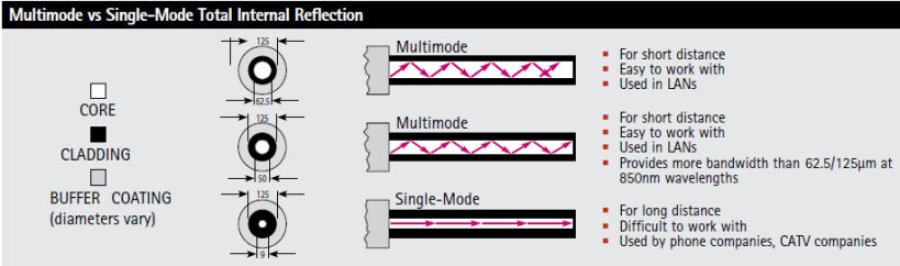
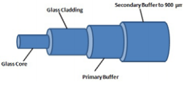
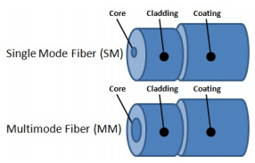
Optical fiber for telecommunications consists of three components: core, cladding and coating. The core is the central region of fiber through which light is transmitted. In general the telecommunications industry uses sizes from 8.3 micrometers (µm) to 62.5 micrometers. The standard core sizes in use today are 8.3 µm (single mode), 50 µm (multimode), and 62.5 µm (multimode). The diameter of the cladding surrounding each of these cores is 125 µm.
To put these sizes into perspective, compare them to a human hair, which is approximately 70 µm or 0.0003 inch. The core and cladding are manufactured together a single piece of silica glass with slightly different compositions and cannot be separated from one another. The glass does not have a hole in the core but is completely solid throughout. The third section of a fiber cable is the protective outer coating. This coating is typically an ultraviolet (UV) light cured acrylate applied during the manufacturing process to provide physical and environmental protection for the fiber. During the installation process this coating is stripped away from the cladding to allow proper termination to an optical transmission system. The coating size can vary, but the standard sizes are 250 µm or 900 µm. The 250 µm coasting takes less space in larger outdoor cables, while the 900 µm coating is larger and more suitable for smaller indoor cables.
 |
 |
Types of Fiber
Once light enters a fiber cable, it travels in a stable state called a mode. There can be from one to hundreds of modes depending on the type of fiber. Each mode carries a portion of light from the input signal. Generally speaking, the number of modes in a fiber is a function of the relationship between core diameter, numerical aperture and wavelength.
Every telecommunications fiber cable falls into one of two categories: single mode or multimode. It is impossible to distinguish between single mode and multimode with the naked eye. There is no difference in outward appearance, only in core size. Both fiber types act as a transmission medium for light, but they operate in different ways, have different characteristics and serve different applications.
Single Mode (SM) fiber allows for only one pathway, or mode, of light to travel within the fiber. The core size is typically 8.3 µm. Single mode fiber cables are used in applications where low signal loss and high data rates are required, such as on long spans where repeater/amplifier spacing needs to be maximized. When jacketed as a single fiber or zipped dual fiber, Single Mode Fiber almost always features a yellow outer jacket.
Multimode (MM) fiber allows more than one mode of light. Common MM core sizes are 50 µm and 62.5 µm. Multimode fiber is best suited for shorter distance applications. Where costly electronicsare heavily concentrated, the primary cost of the system does not lie with the cable. In such acase, MM fiber is more economical because it can be used with inexpensive connectors and LEDtransmitters, making the cost lower for the total system. This makes MM fiber the ideal choice for shorter distance, low bandwidth applications. When jacketed as a single fiber or zipped dual fiber, Multimode fiber almost always has an orange outer jacket.